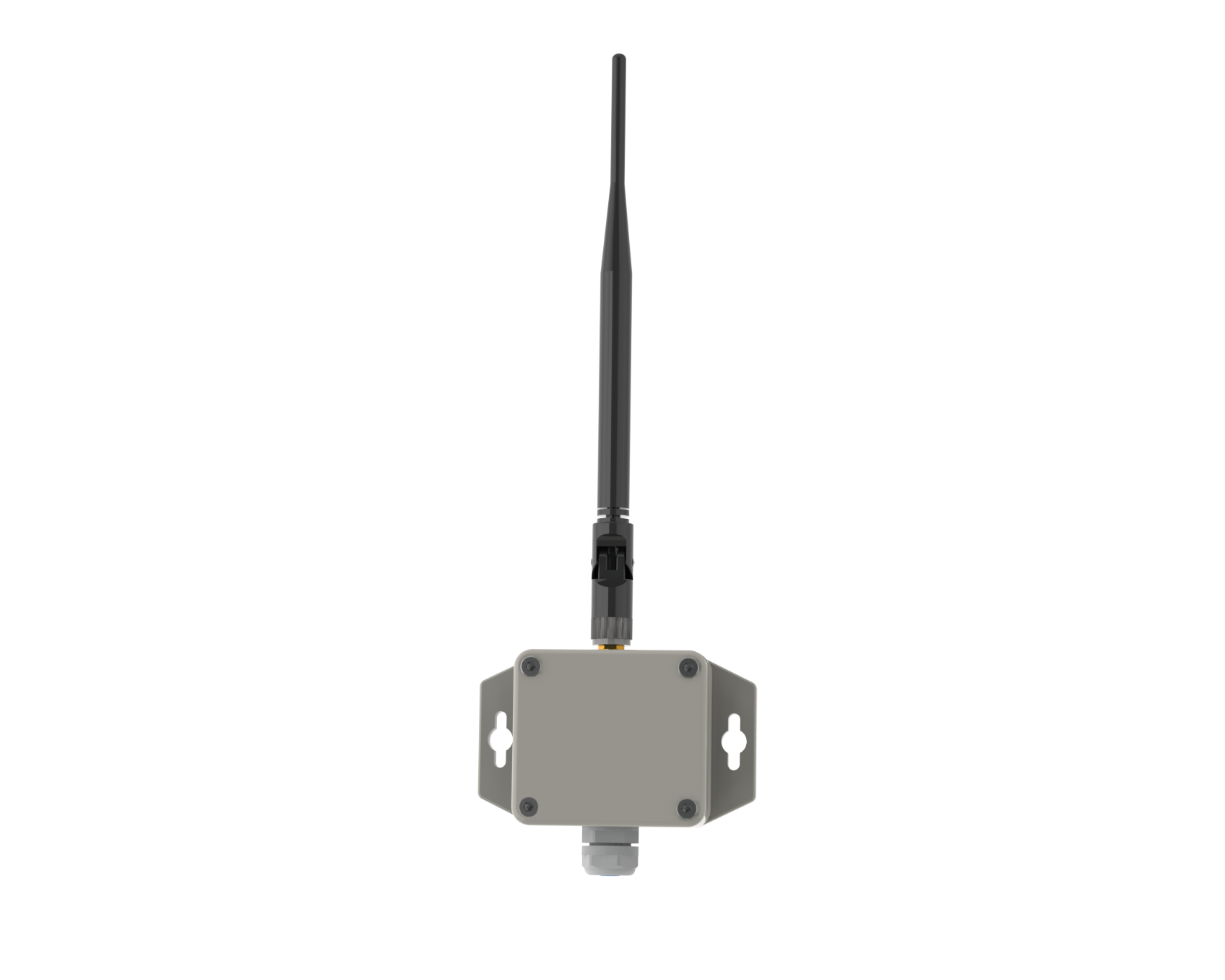
ELT-1/ELT-2-HP
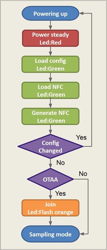
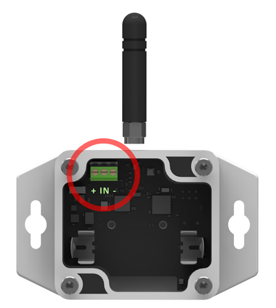
ELT-1 and ELT-2-HP are general LoRaWAN™ devices for measuring analogue or digital signals. ELT-1/ELT-2-HP can for example be used together with electricity meters, flow meters, analogue sensors, moisture sensors, temperature sensors, water leak cable or ultrasonic distance sensors. They are enclosed in an IP65 box and are designed to be outside. Inside the ELT-1/ELT-2-HP you will find three internal sensors: a temperature sensor, a humidity sensor and an accelerometer for orientation measurements. On the ELT-2-HP you will also find an additional atmospheric pressure sensor. They are powered by a 3,6V AA lithium battery. The Battery life is estimated to be up to 10 years but depends on sample interval, transmit interval, data rate, power output and environmental factors. You are welcome to use our online battery lifetime calculator. All Elsys sensors are equipped with NFC (Near Field Communication) for easy configuration with an Android phone. With our application “Sensor Settings“, you can change sample rate, data rate, encryption keys, triggers, activation and much more. All of our sensors are built on the LoRaWAN™ stack from Semtech. Channel planes exists for US902-928, EU863-870, AS923, AU915-928, KR920-923.
Extra features on the ELT-2-HP:
- Dual external connections. This makes it possible to do for example: External temperature + door switch
- Higher maximum output power.
- Internal atmospheric pressure sensor.
Specification
- Analog 0-10V in
- Digital in
- Pulse counter
- Direct connection to S0 outputs
- Direct connection to Decagon moisture sensors
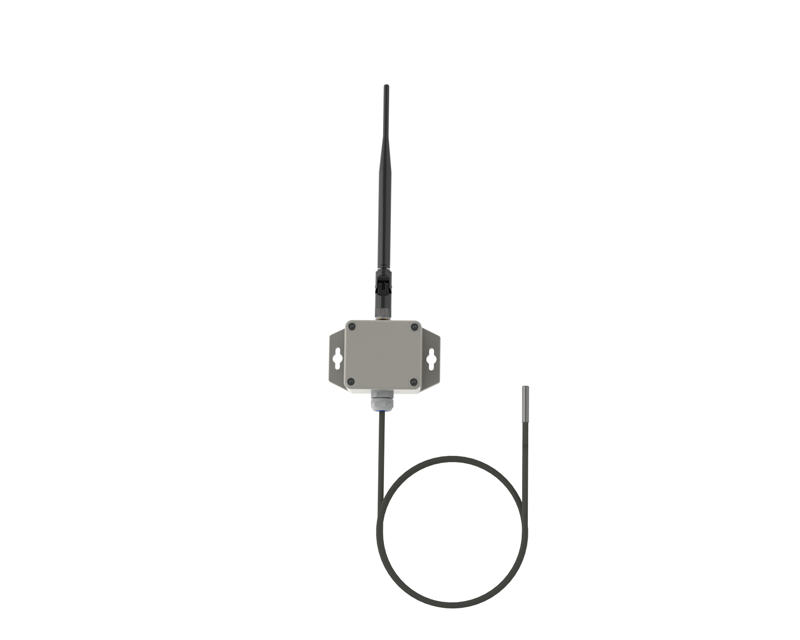
- Direct connection to external temperature sensor
- Water leak sensor input
- Direct connection to distance sensor (ultrasonic)
- Embedded sensors for temperature, humidity, acceleration.
- Embedded atmospheric pressure sensor (ELT-2-HP)
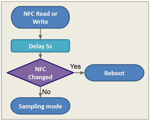
- NFC for easy configuration
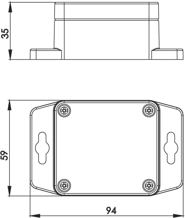
- Size: 94 x 59 x 35 mm
- Output power: +14dBm (ELT-1), +20dBm (ELT-2-HP)
- Approx. range: 8km (ELT-1), 12km (ELT-2-HP)*
- Battery life: 10 years**
- Custom SW possible
- 3.6V AA lithium battery
- US902-928, EU863-870,AS923,AU915-928,KR920-923
* LoRa™ modulation SF10
** Depending on interval
Supported external sensors:
- Analog input (0-10V)
- Pulse input (pullup/pulldown), e.g. power meters.
- DS18B20, 1-wire temperature sensor
- Switch, normally open
- Digital input
- Decagon 10HS, water moisture sensor*
- Water leak sensor/cable*
- Maxbotix, ultrasound distance sensor*
- GPS, with serial output*
*Only supported in firmware versions 2.1.x
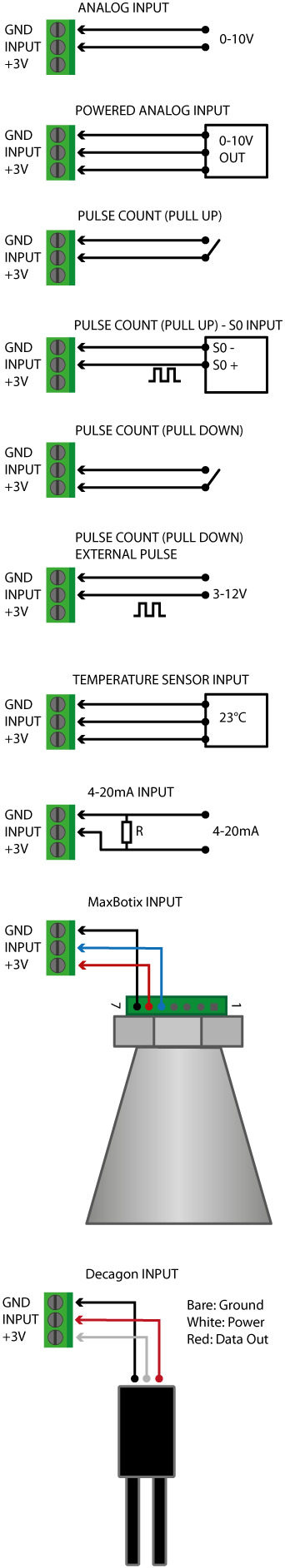
ELT-1 Connection
Analog input
Analog input (0-10V), input signal between input and ground.
Select “Analog input” in android application “Sensor Settings”.
ELT-1 input is internally pulled down and the input impedance is 7.4 kohm.
Powered analog input
Analog input (0-10V), input signal between input and ground. +3V present at B+ pin.
Select “Analog input” in android application “Sensor Settings”. Select “Eternal startup time” in “Sensor Settings” and configure ON-time for sensor. External startup time is how long the sensor will be powered before sampling value.
ELT-1 input is internally pulled down and the input impedance is 7.4 kohm
Pulse count (pull up)
Pulse count input, input signal between input and ground
Select “Pulse input(pull up)” in android application “Sensor Settings”
ELT-1 input is internally pulled up by ~50 kohm*.
Pulse count (pull up) -S0 input
Pulse count input, S0 signal between input and ground
Select “Pulse input(pull up)” in android application “Sensor Settings”
ELT-1 input is internally pulled up by ~50 kohm*.
Pulse count (pull down)
Pulse count input, input signal between input and B+. Select “External startup time” in “Sensor Settings” and configure ON-time for always on that is >100000ms.
Select “Pulse input(pull down)” in android application “Sensor Settings”
ELT-1 input is internally pulled down by ~50 kohm*.
Pulse count (pull down) – External pulse
Pulse count input, input signal between input and GND. Pulse signal from 3 to 12 voltage.
Select “Pulse input(pull down)” in android application “Sensor Settings”
ELT-1 input is internally pulled down by ~50 kohm*.
Temperature sensor input (Rev B)
Temperature sensor input. ELT-1 is configured for 1-wire interface. Connect a DS18B20 compatible sensor.
Select “Temperature input” in android application “Sensor Settings”
ELT-1 input is internally pulled up by 2.2k.
*For lower values, e.g. if there are long cables, this can be adjusted with an external resistor in parallel.
4-20mA input
4-20mA sensor input. Select “Analog input” in android application “Sensor Settings”
Connect resistor parallel to the input. Value of R can be calculated as R=UxI. For full range, use 500 ohm resistor. (20mA will then read as 10V)
Maxbotix ultrasonic range sensor
ELT-1 is configured for Maxbotix ultrasonic sensors. Connect a Maxbotix sensor with TTL or RS232 output.
Select “Distance sensor Maxbotix” in android application “Sensor Settings”
Decagon sensors
ELT-1 is configured for Decagon soil moisture sensor. Connect a Decagon sensor of type EC-5 or 10HS.
Select “Decagon” in android application “Sensor Settings”
Customer installation
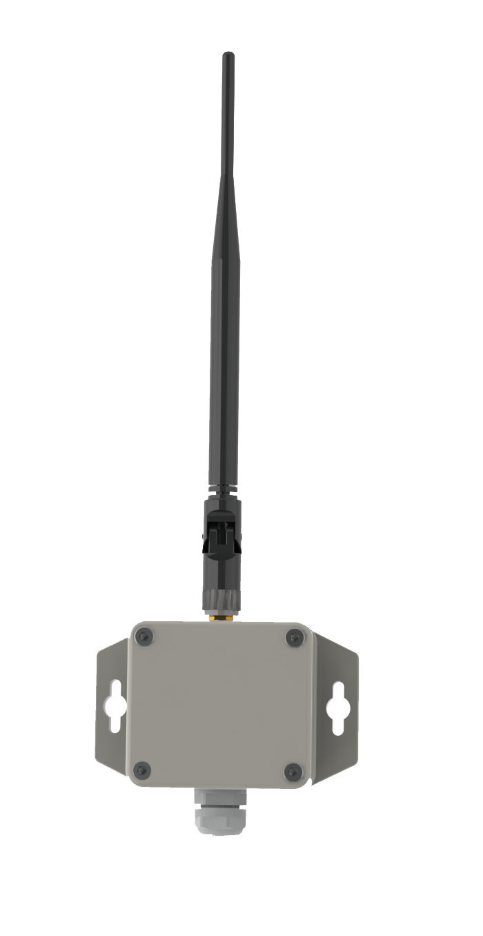
Elt-1, standard 1/2 wave antenna
Elt-1 and external temperature sensor